Dissecting OpenPLC’s Modbus TCP Communications With Wireshark
The first step in every attack consists of a reconnaissance of the environment in order to identify vulnerabilities and attack vectors. Usually, attackers will use Nmap to discover the devices and open ports in the network, but in this case, we will start with a passive network listening method via Wireshark.
Dissecting OpenPLC Communications
Traffic Capture
In order to capture traffic between OpenPLC and FactoryIO, it is necessary to open a terminal in the attacker machine and turn on Wireshark:
sudo wiresahrk
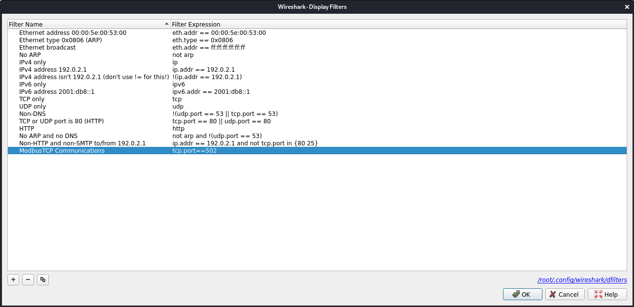
Once Wireshark is opened, it is recommended to add a new filter that can be used to improve the data visualization by showing only traffic against port 502 (default port for Modbus TCP).
Now, we can start listening to the network traffic with Wireshark, turn on the OpenPLC by clicking the “Start PLC” button on the web interface, and you will start to see some traffic being captured. After some seconds, there should be enough data captured in order to analyze OpenPLC’s communication loop.
If no traffic is being detected, make sure the network adapter of the attacker machine is configured properly to allow promiscuous mode.

Stop the data capture and save it somewhere, so it can be accessed later on if needed.
Traffic Analysis
Now let’s start analyzing the traffic captured in order to understand the communication loop used by OpenPLC. This information can very relevant for an attacker as it may point out some vulnerabilities or attack vectors to exploit.
Analyzing the Communication Loop
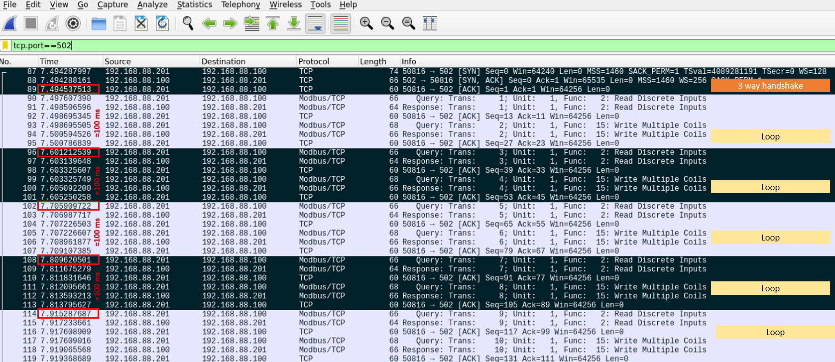
By direct observation of the traffic capture, one can see that:
The first communication between OpenPLC and FactoryIO is a 3-way handshake:
- OpenPLC -> FactoryIO: SYN
- FactoryIO -> OpenPLC: SYN/ACK
- OpenPLC -> FactoryIO: ACK
From that point, there is a communication loop that repeats indefinitely using a typical Modbus TCP query-response structure:
- Read Discrete Inputs
- Query OpenPLC -> FactoryIO: query the status of the sensors
- Response FactoryIO -> OpenPLC: responds with the status of the sensors
- ACK OpenPLC -> FactoryIO: confirms that the response was received correctly
- Write Multiple Coils
- Query OpenPLC -> FactoryIO: asks to modify the status of the actuators
- Response FactoryIO -> OpenPLC: responds that the actuators were modified correctly
- ACK OpenPLC -> FactoryIO: confirms that the response was received correctly
The time between communication loops should approximately match the polling value configured under the “Settings” tab in OpenPLC (100ms in this case).
If the control logic for the PLC would use registers (instead of only discrete inputs and coils) it should be expected to find also some query-response pairs to check and update the registers.
Analyzing Modbus Query-Response Messages
With the general communication logic figured out, it is time to step down a level and look at each individual Modbus TCP message in order to understand its structure:
Read Inputs
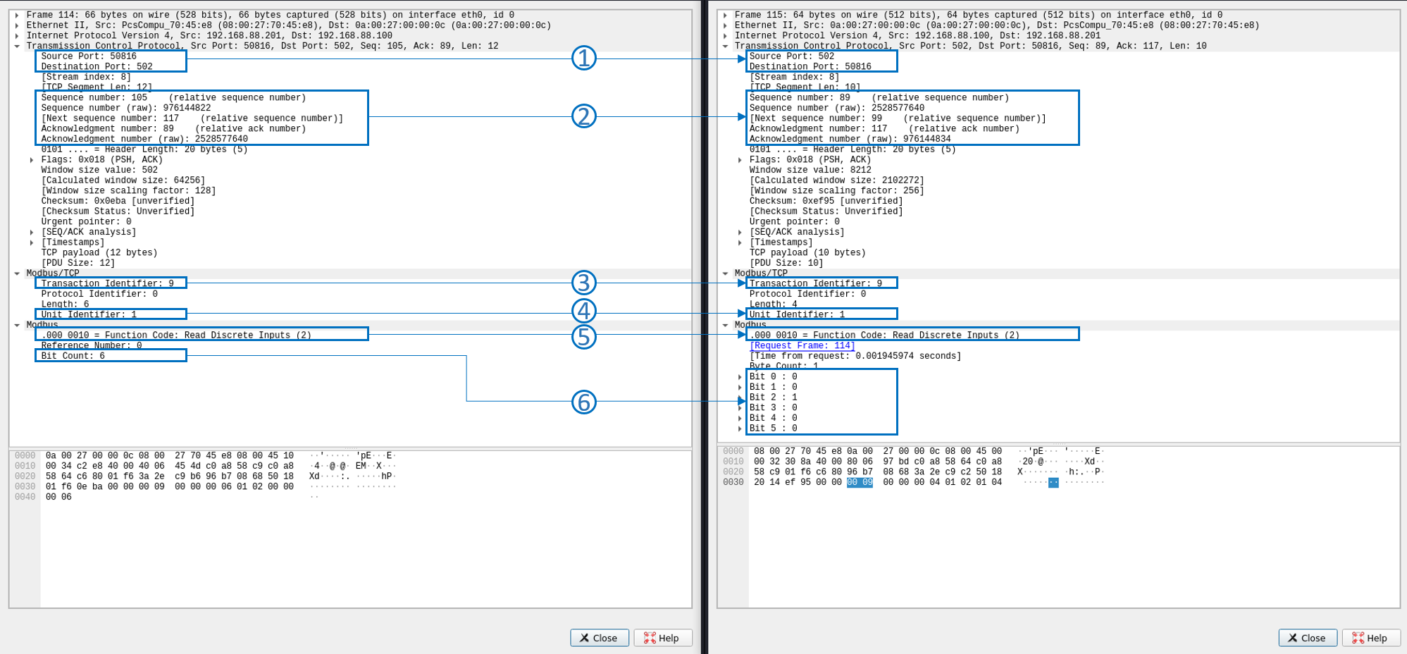
- Analyzing the TCP layer, it is possible to identify the ports used by both devices in the communications. It is interesting to observe that FactoryIo uses the defined 502 port while OpenPLC is using a random one
- Between the Modbus query and the response, there is no ACK. They are sequential
- Modbus TCP uses the same Transaction ID for both the query and the response
- The message intended and responded by the RTU with the ID 1 (in this case there is only 1 RTU, but in real environments, there may be more of them)
- The function used is number 2 (000 0010 in binary), which matches standard Mobus function codes
- The query requests to read 6 inputs (Bit Count) starting at 0 (Reference Number). The reason for this is that both the Driver in FactoryIO, and OpenPLC’s slave device are configured to have a total of 6 inputs. The response to the query shows the state of each input (1=on, 0=off), but it is not possible to know to which sensor is assigned (safety door, box detection, etc.)
Write Coils
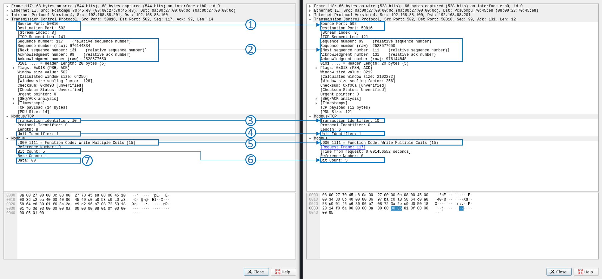
- Analyzing the TCP layer, it is possible to identify the ports used by both devices in the communications. It is interesting to observe that FactoryIo uses the defined 502 port while OpenPLC is using a random one
- Between the Modbus query and the response, there is no ACK. They are sequential
- Modbus TCP uses the same Transaction ID for both the query and the response
- The message is intended to and responded by the RTU with the ID 1 (in this case there is only 1 RTU, but in real environments, there may be more of them)
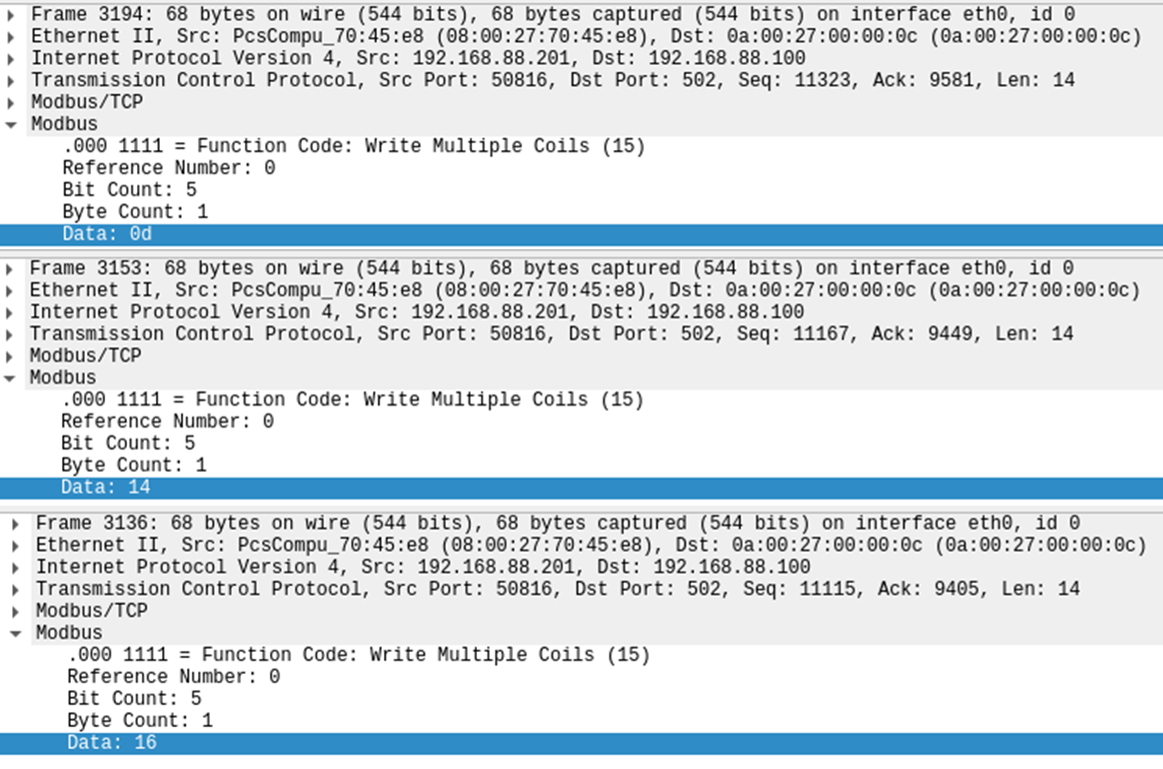
- The function used is number 15 (000 0111 in binary), which matches standard Mobus function codes
- The query requests to write 5 coils (Bit Count) starting at 0 (Reference Number). The reason for this is that both the Driver in FactoryIO, and OpenPLC’s slave device are configured to have a total of 5 coils (outputs)
- The requested status for the coils will be 00. There are other values found for this data on different frames of the capture (14, 16, 0d, etc.) which signals the usage of a hex to binary translation in order to reflect the target status for the actuators.

Observation Summary
After al the analysis, it is possible to make the following observations:
- The connection between OpenPLC and FactoryIO starts with a 3-way handshake
- Messages use the common TCP protocol ACK Number and Sequence Number
- Each Modbus response triggers an ACK from the destination system
- It is possible to know the destination RTU of a message by checking the “Unit Identifier” of the Modbus TCP payload
- Modbus messages use a sequential number (Transaction Identifier) that increase with the queries but not with the responses
- It is possible to know the intent of a query/response because OpenPLC uses standard Modbus functions
- It is possible to know the current state of the sensors by analyzing the payload of the Read Inputs response
- It is possible to know the target state of the actuators by analyzing the payload of the Write Coils query
- The Write Coils uses Hex to Binary translation to reflect the target status of the outputs
- It is not possible to know which sensor or actuator is associated with a certain value just by analyzing the payload
- All of this is possible because ModbusTCP is not an encrypted protocol
All of this information may appear harmless now but will be very valuable later on in order to decide on an effective attack vector.