Virtual Industrial Cybersecurity Lab – Part 3: Simulating the Physical Process with Factory IO
In the previous post, we saw how to install OpenPLC and ScadaBR. Now I will focus on the physical process simulation with FactoryIO.
Before starting, it is necessary to remember that the objective for this lab is to build a suitable testbed that contains some of the key industrial automation elements and use it for further security testing. For that reason, a full-fledged simulation that follows automation guidelines and best practices is out of the scope. We want to learn cybersecurity, and this is just a means to the end.
With this in mind, I have tried to reach a compromise between functionality and realism (especially in the communication arena) without investing too much time in it. Time is limited and better used for security testing.
With that out of the way, let’s start:
Download and Install FactoryIO
The platform used for this simulation is FactoryIO. You can download a 30 day trial version on their webpage.
There are different modules packages that can be acquired (OPC-UA, Modbus TCP, S7, etc.) if you are looking to buy the software, but for our lab, we will need the one with Modbus TCP at least. Nevertheless, this is not an issue with the trial version as it contains all of the packages.
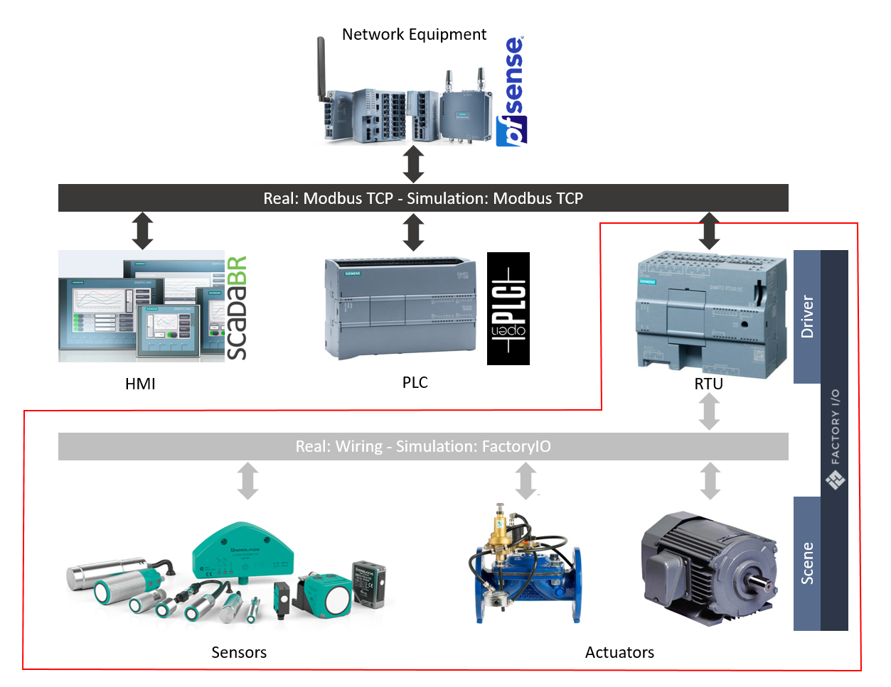
FactoryIO is going to serve a double function:
- Scene: simulates the physical process, with all of the sensors and actuators needed
- Driver: simulates the RTU (Remote Terminal Unit), communicating with OpenPLC via Modbus TCP, and controlling all sensors and actuators in the scene.
Physical Process Simulation – Scene
Before starting the simulation, it is very useful to have at least a high-level definition of what we want to accomplish. In our case it goes as follows:
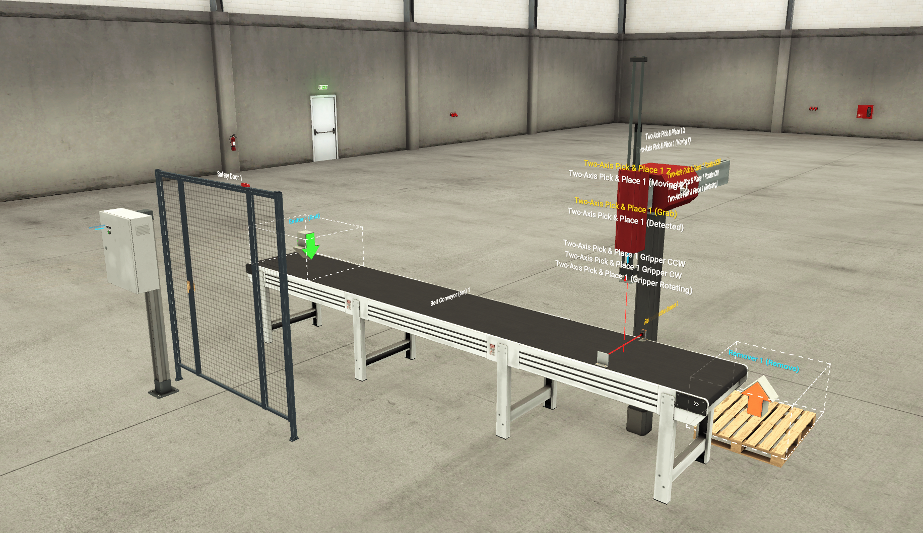
- A conveyor belt transports boxes to a collection point, signed by a light emission and a retroreflective sensor
- When the system detects a box at that point, the conveyor belt stops, and a robot picks it, moving it away from the belt into the floor.
- The access to the production line is controlled by a safety door, that will stop all movement in the line if it is opened while the line is running.
We download and install the software, and create a new scene to start placing all of the physical elements in it (see full list below). I am not going to go into detail about how to use FactoryIO, as there is a very detailed documentation on their page.
- Emitter: element that will create the boxes at the start of the line
- Start Button: it will be used to start and stop the line. I a real situation, there will be some more buttons such as emergency stop, reset, etc. but for simplicity reasons I will use only that one.
- Safety Door: this door has a sensor that can detect when it is opened or closed. It limits access to the danger zone posed by the moving robot to factory personnel. In a real situation, the whole area may be limited with some fence, but I will just place the door so it does not obstruct visibility of the process.
- Conveyor Belt: moves the boxes from the creation point to the pick point
- Light Emitter: continuously emits a beam of light
- Retroreflective Sensor: detects the light emitted by the element above in order to determine when a box is ready for recovery.
- Pick and Place Robot: picks the boxes and moves them out of the conveyor belt. Probably the most complex device on the scene, as it has a built-in set of sensors and actuators. However, this exercise only makes use of the following:
- Grab: turns on the suction head to pick the boxes
- Detected: detects if the suction head is making contact with any box
- 1Z: extends/retracts the robot arm in the Z-axis
- Moving Z: detects whether the robot is moving on the Z axis
- Rotating: detects whether the arm (not the grabbing head) is rotating
- Rotate CW: rotates the arm (not the grabbing head) clockwise
- Rotate CCW: rotates the arm (not the grabbing head) counter-clockwise
- Remover: element the will remove the boxes from the scene once they reach the end of the line
- Additional: just of visualization purposes, they do not have any specific function
- Pallet: a place for the boxes to fall
- Column + Electric Switchboard: a place where to place the start button
If you have placed all of those components, now you should have a nonmoving scene that looks something like this:
RTU Simulation – Driver
With all the elements placed on the scene, we can now proceed to setup the driver that will communicate with OpenPLC in FactoryIO, for that:
- Access the driver menu by pressing F4 in the scene
- Select Modbus TCP/IP Server as driver
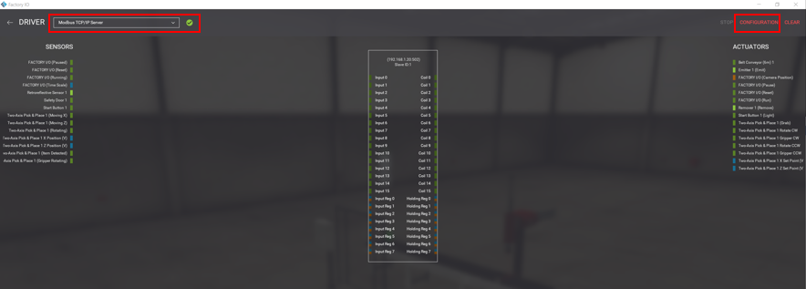
- Click on the top right left to configure it
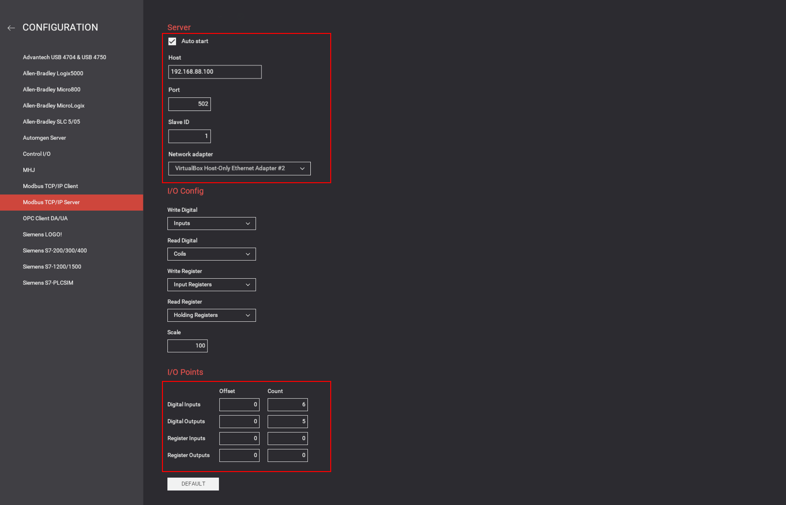
- Server:
- Network Adapter: select the virtual adapter created in part 1
- Host: configured automatically when selecting the network adapter
- Port: 502 (default Modbus TCP)
- SlaveID: anyone you want
- I/O Config: by default
- I/O Points: the simulation just uses 6 sensors, and 5 actuators (no registers), so we configure the values appropriately (6,5,0,0) and press back to do the final step. If you want to use more sensors or actuators, adjust this number accordingly.
- Server:
- Drag the sensors and the actuators to each one of the places in the driver, in a way that all of them have something assigned.
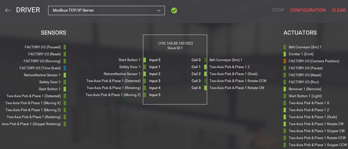
- Go back and save the scene
Congratulations!
If you have made it this far, you already have a physical process ready to be controlled from OpenPLC. If you want to know how, keep reading!