Virtual Industrial Cybersecurity Lab – Part 4: Programming the Control Logic
In the previous post, we saw how to simulate the physical process with Factory IO. The last step before it is possible to start using the lab for some initial security testing (at least on a reduced state without HMI), will be to program the control logic that orchestrates the scene and integrate FactoryIO with OpenPLC via Modbus TCP:
Integration of OpenPLC with FactoryIO
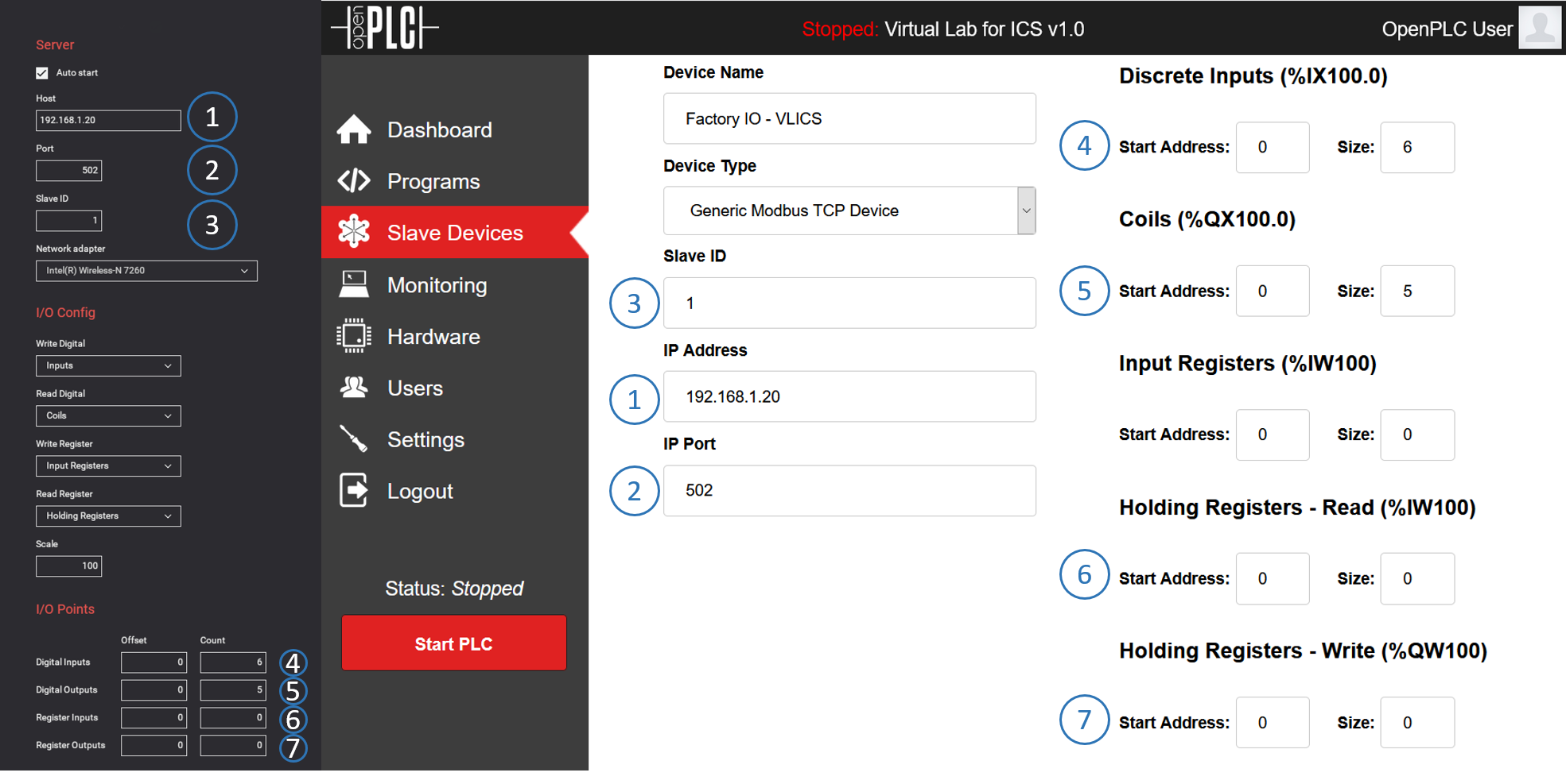
To integrate FactoyIO with OpenPLC, we need to access the web portal for OpenPLC (remember, in this case it is 192.168.88.201:8080). Once inside access the tab “Slave Devices” to configure the FactoryIO driver as a Slave Device for OpenPLC, keeping in mind the following considerations:
- Device type: must be generic Modbus TCP device
- SlaveID: can be any number, but must coincide with the one previously configured in the driver for FactoryIO
- IP Address: same address configured in the FactoryIO driver
- IP Port: 502 is the default ModbusTCP port, it is recommended to keep it by default, even though it is possible to change it as long as it is the same in OpenPLC ad FactoryIO driver.
- DiscreteInputs: starting at 0 and ending in the number of sensors (digital inputs) that we have (in our case 6)
- Coils: starting at 0 and ending in the number of actuators (digital outputs) that we have (in our case 5)
- Input registers: there are no registers in our lab, so can be configured as 0
- Holding Registers – Read: there are no registers in our lab, so can be configured as 0
- Holding Registers -Write: there are no registers in our lab, so can be configured as 0
Programming the Control Logic
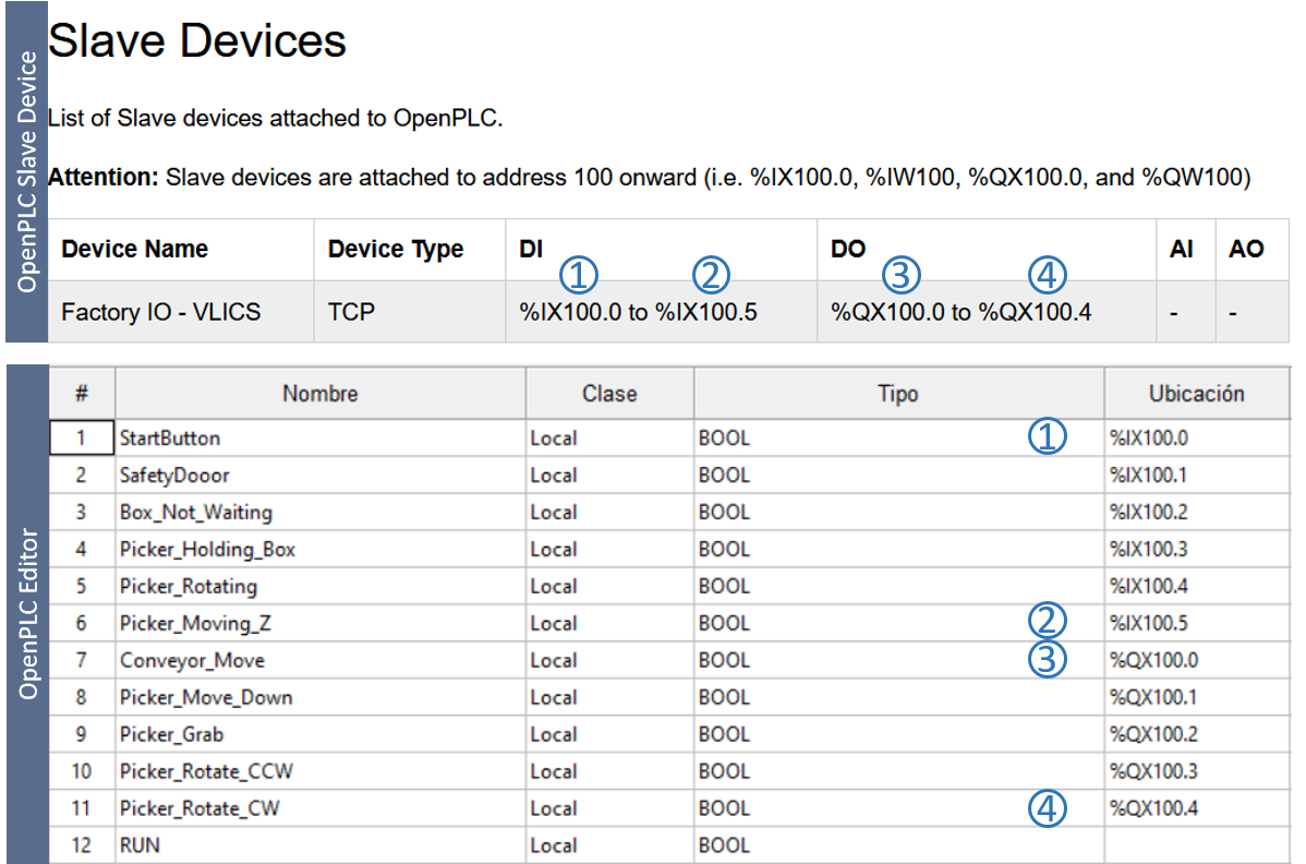
OpenPLC Editor is the tool used to program the control logic of the lab. This is a separate program from OpenPLC Runtime and can be downloaded and executed directly in the Windows10 host machine. Once downloaded, start a new project (more info on that here) and create the variables to be used having in mind the following considerations:
- The variables declared in OpenPLC Editor must fall inside the range available by the Slave Device configured in the previous point
- There is an auxiliary variable called “RUN” that will not be assigned to any input (%IX100.x) or output (%QX100.x)
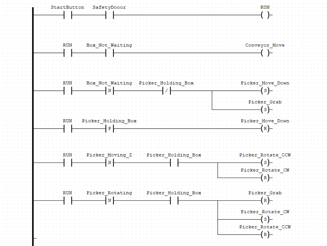
With the variables already defined, it is possible to now proceed to develop the control logic, using for that purpose one of the standards in the sector (Ladder Logic). On a high level, the program will fulfill the following criteria:
- Pressing “StartButton” starts or stops the line
- Opening the Safety door will stop the line
- The line stops when there is a box waiting
- If there is a box waiting, the robot will start the suction hed, descend, rotate away from the conveyor belt, drop the box, and go back to its initial location
I want to highlight that the program shown below does not follow automation coding standards and best practices but nevertheless, it is completely functional and serves its purpose (controlling the line) adequately.
Run Time
We are very close to the moment of truth, and there are just a few more steps to finish:
- Export the control logic in OpenPLC Runtime as an .ST file
- Turn on the virtual pfSense router
- Turn on the OpenPLC’s virtual machine
- Using your host machine web browser, access the web application for OpenPLC (192.168.88.201:8080)
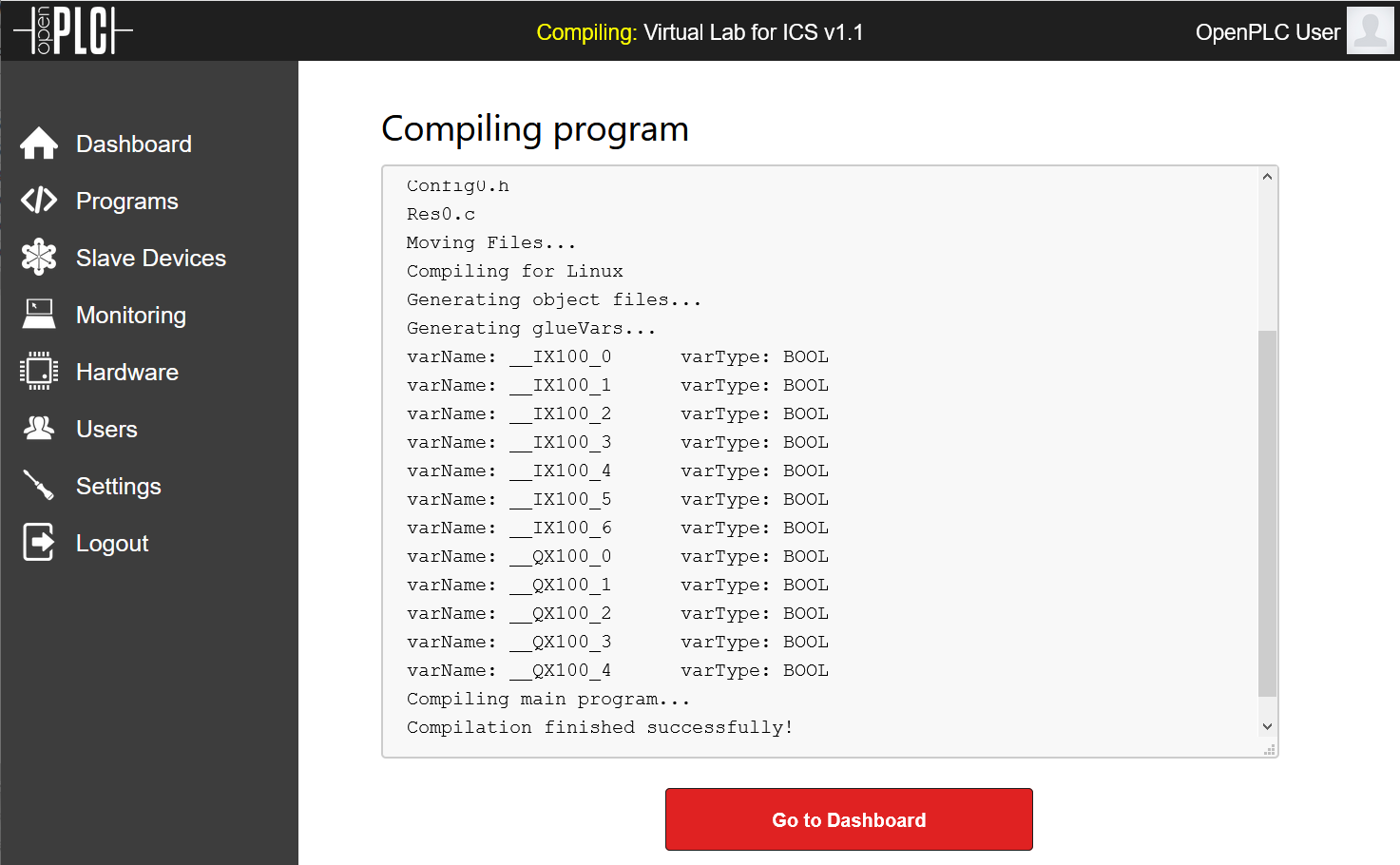
- Login and access the “Programs” tab, upload the .ST file. If everything went well, you will see the following confirmation:
- Now, it is time to turn on FactoryIO and open the scene created in the previous post and press the play (run mode) button
- From OpenPLC’s dashboard, click on “Start PLC”
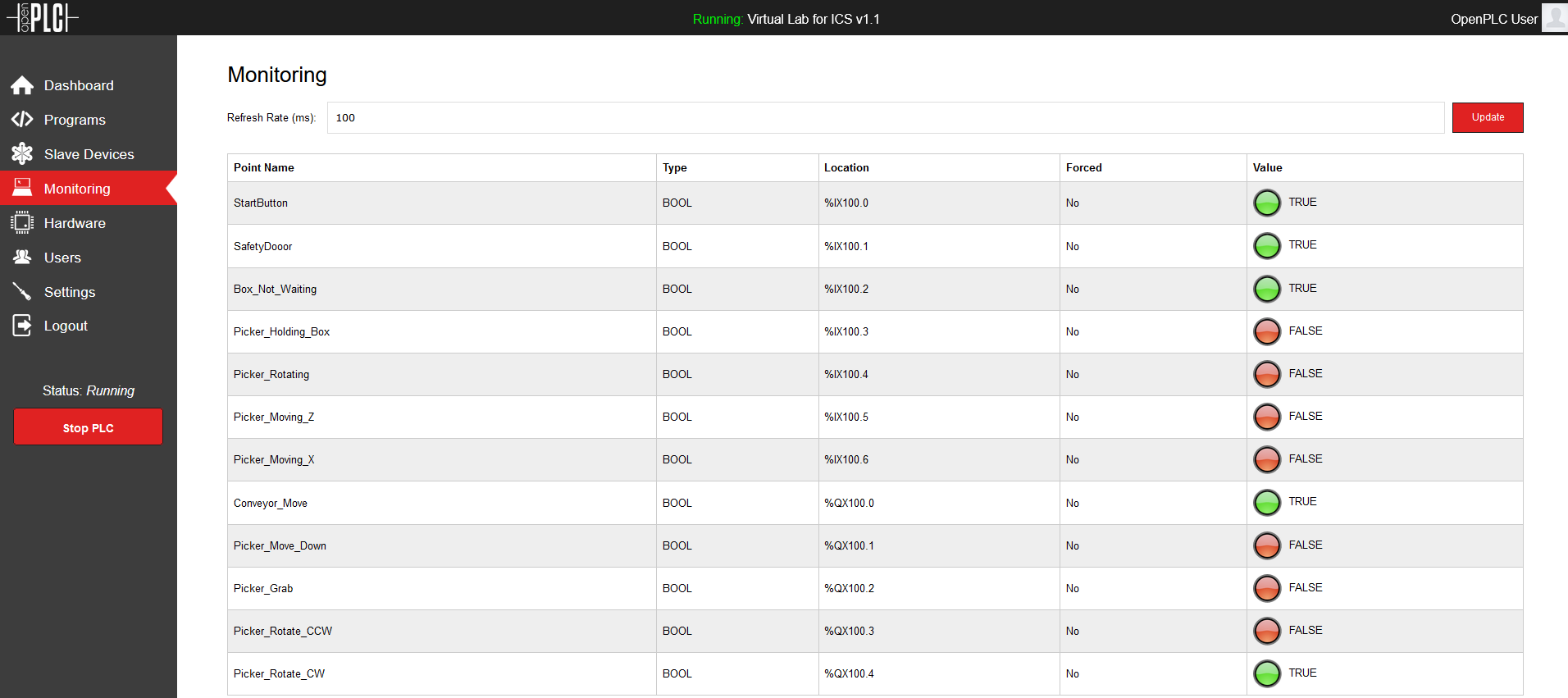
- At this point, the scene should be static but you should be able to see all the states for sensors and actuators in FactoryIO from the “Monitoring” tab in OpenPLC
- As a last step, go to FactoryIO, press the StartButton on the scene, and you will see your lab come to life!